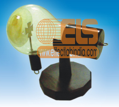
When the cross is placed in the path of the cathode rays, a sharp shadow is formed. Its sharpness is an indication that the rays are emitted from the cathode in a definite direction and not like from a luminous surface in all direction. It shows that the cathode rays travels in straight line.
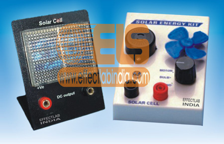
A very versatile and illustrative teaching tool this kit permits the students to use solar energy in an interesting and practical manner. The kit consists of a solar panel housed in a plastic box. It also includes, a low consumption motor with fan, Buzzer, L.E.D. this kit demonstrates the conversion of solar energy in all sorts of energy tangible outputs like light, sound and blowing wind.
These are built in nicely finished steel, cabinets having lock type terminals, On/Off switch, and jewel light. Full wave bridge rectifiers, double wound transformers are used with copper wire and high-grade laminations to avoid losses. Input 230 volts 50 Hz. A.C. and output 2,4,6,8,10 and 12 V D.C.
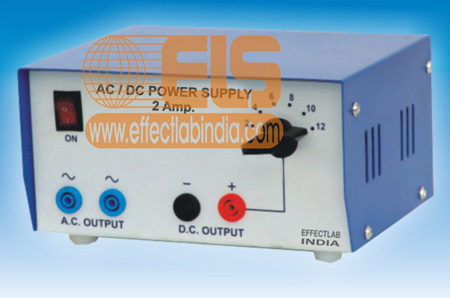
This unit provides A.C./D.C. voltages in 2V steps up to 12V. The A.C. is rectified to give the D.C. equivalent. An automatic electronic circuit breaker gives protection against electrical overload or short circuit. The circuit breaker opens when the rated current is exceeded . Separate A.C. and D.C. socket terminals allow 4 mm. plug to be used for connection to the output. Connection to the mains lead, supplied with each unit. The unit is enclosed in a ventilated power coated steel cabinet
Main Input :
220/230 Volts 50Hz.
Voltage Output :
A.C. 2, 4, 6, 8, 10, 12V full wave rectified equivalent
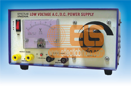
The most versatile power supply that can fulfil most of the requirements of a physics laboratory. It provides continuously variable A.C. and D.C. voltage output. A meter is provided to indicate both A.C. and D.C. voltages. An internal fuse is provided for input and a resettable cut-out for output. The unit is enclosed in a ventilated power coated steel cabinet. With detachable 1.5 metre mains lead.
Specifications
Output Voltages :
0 to 25V A.C. and under smoothened full wave rectified D.C.
Voltage Selection :
Rotary continuously variable transformer operated by a large knob on front panel.
Output Display :
A.C. and D.C. output voltages by a moving coil meter with selector switch to select A.C. and D.C.
Circuit Protection :
Mains input 3A internal glass fuselink. Output is protected by a resettable cut-out.
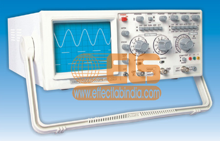
The 25 MHz oscilloscope are dual-channel oscilloscope with maximum sensitivity of 5mV/DIV. The time base provides a maximum sweep time of 0.2 uS/DIV. when magnified by 10, the sweep speed is 20nS/DIV. Each of these oscilloscope employs a 6-inch rectangular type cathode-ray tube with red internal graticule. These oscilloscope are sturdy, easy to operate and exhibits high operational reliability.
Features :
Max. Vertical Sensitivity 1 mV/divÂ
Alternate trigger
TV-V, TV-H Sync Separator
Max. TB Speed
Z axis TTL Level
Â
Technical Specification :
Vertical Axis
Bandwidth :
DC-25 MHz
Deflection Coefficients :
5mV/div-20V/div, 12 steps in 1-2-5 sequence Variable Continuously Variable to 1/2.5 or less than panel-indicated value